Industrial Ventilation - 3. Ducts
On this page
What is covered in this document?
Back to topThis document is part of a series of documents on industrial ventilation. This document covers the basic principles of duct design.
What is a duct system?
Back to topThe ventilation system in a building consists of air-moving devices such as fans and blowers and a network of ducts that exhaust the contaminated indoor air and bring in air from outside the building. Ducts are channels, tubes, or pipes that carry moving air.
What are some basic principles of duct design?
Back to topDuct systems should be designed to have airflow through the ducts with as little friction or resistance as possible. The amount of air that flows through a duct depends on the cross-section area (duct opening area) of the duct and the air speed. Air moving too slowly will allow contaminants such as dusts to settle and accumulate. These particles will eventually clog the duct. Air moving too fast wastes power, can create noise problems, and may cause excessive abrasion, especially in branches and elbows, due to increased friction between the air transporting dust particles and the duct. Recommended speed ("duct velocity") for different contaminants can be found in reference books on ventilation.
Duct systems typically require large amounts of air to move relatively small amounts of contaminants. The required volume of airflow depends on the acceptable concentration of air contaminants inside the workspace. A carefully designed system can achieve the required air concentration while using the least amount of power. Other design considerations include initial capital costs, reliability, maintenance, and durability of air handling equipment.
The table below illustrates some basic duct design principles.
| Duct Design Principles | ||
|---|---|---|
| Principle | Design for less resistance for airflow | Avoid design that causes more resistance to airflow |
| Streamline the system as much as possible to minimize air turbulence and resistance. | 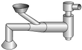 | 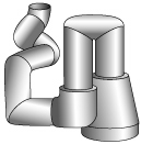 |
| Round ducts provide less resistance than square ducts (less surface area). |  |  |
| Smooth, rigid ducts provide less resistance than flexible, rough ducts. |  |  |
| Short runs of ducts provide less resistance than long runs. |  |  |
| Straight runs offer less resistance than runs with elbows and bends. |  | 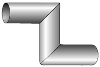 |
| Duct branches should enter at an angle of 30° (or less) to 45° rather than right angles, and at a location where the duct expands gradually. |  |  |
| Elbows with gradual bends provide less resistance than sharp bends. | 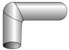 | 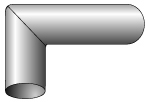 |
| Large diameter ducts provide less resistance than small diameter ducts. |  |  |
What are the main types of duct systems for local ventilation?
Back to topThere are two main types of duct systems: tapered main systems and plenums.
The main duct of a tapered system gets larger as branches are added and flows are merged together. This tapering allows the airspeed to remain almost constant throughout the duct. Due to this characteristic, the tapered duct system is the main system used in local ventilation. (Figure 1)
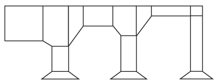
Tapered duct system
In the plenum system, the main duct stays the same size throughout the system. The speed of the air is lower than in the tapered ducts, and sometimes lower than the minimum speed that is required to transport contaminants. For this reason, the plenum system is mainly used only when the separation of particulate matter (large particles or liquid droplets) is intended. Explosive dusts, however, must not be exhausted through a plenum duct system.
One advantage of a plenum system is that new branches can be added anywhere, and the addition is limited only by the total airflow and pressure available at the fan.
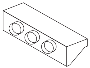
Plenum system
What causes duct leakage or plugging?
Back to topDucts can plug or leak for the following main reasons:
Low airspeed: Inside the ducts, air speed must be in a range that is adequate to move contaminant effectively. Changing the duct size or the airflow rate through any duct can lead to changes in the minimum transport speed. One small change in one section of the system can affect the overall system and its performance.
Flexible ducts: Corrugated flexible ducts create more friction and bend losses that slow down air movement.
Modifications of the duct system: If hoods and ducts are added to the existing duct system, it is necessary to adjust or "rebalance" the airflow. If not properly rebalanced, the system will "self-balance" - typically, the airflow will be reduced in the sections that have higher resistance. Reduced airflow will cause particulates to settle out of the air stream and the ducts to plug.
Particulate traps, settling chambers, or "cleanouts" are not present or used: Frequent cleaning of specific points in the duct network (those that plug first) can reduce the need for a major system cleaning. By monitoring the most common trouble spots, the effort needed to maintain the ducts is minimized. At locations of rapid or frequent plugging, cleanout or access doors make cleaning much easier. See Figure 3.
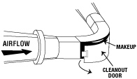
Figure 3
Typical Cleanout Door for Duct Network
Airflow changes direction abruptly: Deposits are more common in short radius elbows and "T" type branch connections. The figures below illustrate what happens when the air direction changes abruptly.
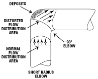
Abrupt Air Direction Change
(Short radius elbows create heavy deposits)
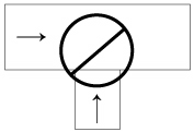
Abrupt Air Direction Change
(Never use "T" Connection)
How do I know if ducts are functioning as designed?
Back to topMost performance problems in a ventilation system are from the improper functioning of the ducts. It is common for a system to be well designed and properly installed, but develop problems as time goes on.
It is necessary to measure airflow and static pressures in the duct network on a regular, scheduled basis to be sure the system is working within its design specifications and to troubleshoot any possible problems. Trained people such as ventilation experts or occupational hygienists using specialized equipment should carry out these measurements.
However, below are some tips for conducting a simple inspection. You will need a drawing of the ventilation system. If you do not have one, make one as you go. While you follow the entire system take note of the following:
- Reduced ability to capture the contaminants ("fugitive" contaminants can be measured or sometimes be seen).
- Constant plugging of a duct. Tap the duct gently with a stick to see if it has layers of build-up,
- Damaged ducts (dents, holes).
- Damaged or missing gaskets.
- Visible dust on equipment connected to the ventilation system.
- Obvious add-ons to the system (especially those that were added on after the initial installation of the system).
- Opened blast gates or other openings.
- Duct cut-offs (covered with blank flanges).
Document any of the above problem(s) and possible causes. Bring these problems to the attention of the building maintenance staff, your supervisor, or a ventilation expert if possible.
- Fact sheet last revised: 2023-06-21
